Pictures of the new hexagonal design for
mini-heliostat arrays
Introduction
The design of the mini-heliostat arrays has been changed
somewhat during the past six months. These pictures have been
sitting around since this summer and it is time that I do something
with them.
Since some of the pictures are rather large, thumbnails will be
presented first. If you want more detail, click on the thumbnail
and the bigger picture will load.
Views of a small field and a tower
 |
 |
 |
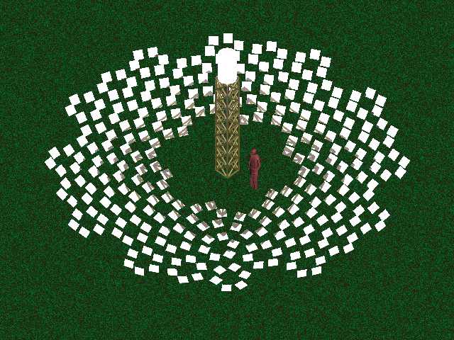
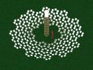
| LEFT: A side view, as seen from the sun. The mirrors are white
since they are reflecting the image of the white-hot boiler from
this angle.
JPEG 62k
|
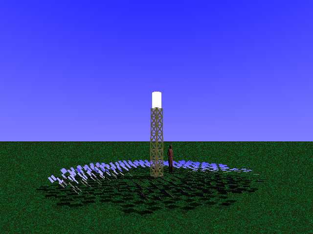
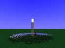
CENTER: A side view, as seen from eye-level about 11 metres
away from the center of the field. The human figure is 180 cm tall.
JPEG 23k
|
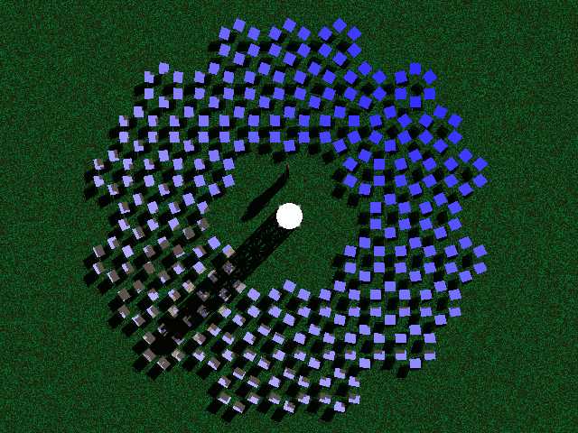
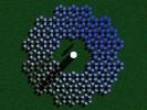
RIGHT: A top view, seen from above the tower. The mirrors are
mostly blue because they are reflecting the sky from this angle.
JPEG 55k
|
Heliostat field specs
The field in these pictures consists of 48 arrays of 6
mini-heliostats each (288 mirrors total) arranged on hexagonal
frames (not shown, but see below). Since the mirrors are 30
cm by 30 cm, this gives a maximum total flux of about 25 kW of
solar energy (assuming a direct insolation of 1 kW/m2
and ignoring cosine factors.)
A human figure has been added to the pictures to give a sense of
scale.
In the center of the field is a 4 meter receiver tower made of
metal with a 1 meter high, 60 cm diameter steam boiler on top. The
boiler could be a recycled high pressure gas bottle or a coil of
steel tubing. The boiler is white due to the concentrated solar
radiation falling on it. The sun is at an elevation of 45° and
an azimuth of 45° and the mirrors are all angled to reflect the
light to the center of the boiler.
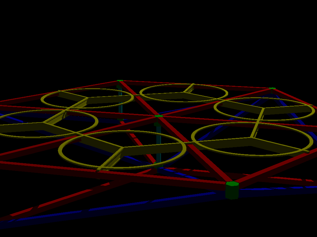
The hexagonal support structure
|
|
PNG 21k
|
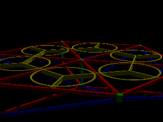
The picture above gives an approximate idea of what the
hexagonal support structure of each array will look like. Note that
it will not be multi-coloured. This frame is mostly
composed of hollow square (or round) plastic tubes, about 1.5 cm in
width with a wall thickness of 1 mm. The largest pieces are 80 cm
long and the array is 160 cm across in its largest dimension. The
combination of the frame plus the plastic heliostats should weigh
about 1 kg.
These tubes are fastened together with specially molded junction
pieces that allow one to snap the structure together - no screws
are needed. The result is a strong but extremely light-weight
structure to which the heliostats, gear trains, and motor units can
be attached. Assembly is simple enough that even a youngster with
average intelligence and dexterity could put together many
structures in an hour.
Deployment of arrays
Array assembly can take place near the field or far away. In
either case, transport is a one-man job since the heliostats and
their supports are so light-weight. A normal adult could easily
carry two assembled arrays at a time or possibly four, if he was
careful.
This ease of transport could important for protecting the
heliostats from storms or other natural disasters. It also permits
use in cases where land is only temporarily available, for
example in fields that farmers have left fallow for a couple of
years.
The arrays are placed on relatively smooth ground surrounding
the central tower. Each array has three legs (not shown above) that
allow the array to rest perfectly stable on the ground without any
preparation. If wind is a problem, the legs have holes in their
feet that allow one to secure the leg with a spike driven into the
ground.
Calibration of arrays
After all of the arrays are placed, their motor units are hooked
up to one or more shared controllers and the field is
calibrated.
If the field is small, the calibration procedure is done
semi-automatically during the day by adjusting two mirrors from
each array with a "teaching wand" (a remote-control joystick that
is interfaced with the controller computers) to reflect the
sunlight to a calibration target. If the field is large, the
calibration procedure is done automatically at night with a
computer-guided laser and a computer vision system.
How the pictures were done
The software (POVRAY) used to render these pictures is described
in the previous page of
renderings.
--
Erik Rossen <rossen@rossen.ch>
OpenPGP key: 2935D0B9
Tel: +41 78 617 72 83
Home URL: http://www.rossen.ch
Copyright © 2000 until the heat-death of the Universe (thanks, Mickey!), by Erik Rossen
Last modified: 2016-02-07T12:43:24+0100
HOME -> SOLAR + HELIOSTATS -> HEXAGONAL HELIOSTAT SUPPORT | SITEMAP