The White Cliffs Solar Steam Engine
The following is an excerpt from a report entitled "The White
Cliffs Project - Overview for the period 1979-89" published by the
Department of Energy of the government of New South Wales in 1991.
Pages 85-90 have been reproduced with the
permission of the NSW DOE.
For more information on this report and where to order a copy,
click here. The NSW DOE has
an on-line order-form and a list of its publications
here.
GOOD NEWS!After having received dozens of requests over the
years for a full version of this report, the NSW government has finally scanned
it and published it online! And just in case they decide to reorganise
again, here is my
local copy.
3.4 The Steam Engine
In recent years much effort has been directed to developing, on
the one hand, high efficiency heat engines (for example employing
Stirling, Brayton and other cycles) for utilizing, very
efficiently, the high quality heat from concentrating solar
collectors; and on the other, to produce very inexpensive low
efficiency steam and other engines which can be built in Third
World workshops and supplied by energy from biomass. The former
objectives have not as yet been realised because problems of
performance, especially reliability and cost effectiveness, have
not been adequately overcome; the latter also for various reasons
have not resulted in that technology reaching significance.
But there is another approach, relevant to these application
areas, which employs medium level technology and is based on
mass-produced readily-available components, supplemented by some
special items to produce steam engines with heat-to-mechanical work
conversion efficiencies of over 20%, robust, reliable, able to be
maintained by those with automotive and agricultural experience,
and having the potential for cost-effectiveness for many
applications.
Such engines have resulted from our development of the White
Cliffs Solar Thermal Power Station [Kaneff 1983, 1987], where a
unit has operated for many thousands of hours giving electricity
supply reliably. Other units are currently working in the USA (in
Troy NY, at Albuquerque NM and at the Sandia test facility,
preparatory to operation on Molokai Hawaii); please see Appendix I.
Further units are to be used for a rural village power supply in
Fiji and for the utilisation of crop wastes in Australia. Figure 41
shows the White Cliffs engine.
3.4.1 Engine Details - Piston Operated Valves (POV)
For reasons already indicated, this unit employs a diesel engine
converted to steam operation. The particular unit employed a Lister
3-cylinder engine - is used in its thousands in Australia and has
the advantage that each cylinder and head is removable.
Most of the engine is made from parts of two diesel engines
(Lister and Ceneral Motors) which are on the market. The general
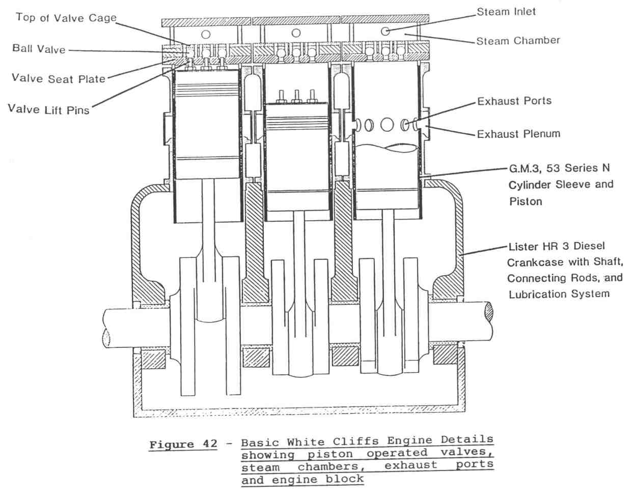
form of the engine is shown in Figure 42.
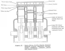
Steam is supplied to a chamber in the head of each cylinder; the
engine is started by a standard electric motor. As a piston
approaches top dead centre, the pins in its crown lift the three
ball valves from their seats and steam enters the cylinder until
the valves seat again past dead centre. The steam expands while
applying pressure to the piston until the piston exposes the normal
exhaust ports in the cylinder liner which was made for a 2-stroke
diesel engine. The cylinders, cylinder heads, valve seats and steam
chambers, that is, the conversion components, can be produced by
relatively simple workshop techniques from cast iron, mild steel
and stainless steel.
All parts of the engine are inexpensive, do not require special
machine tools to fabricate, and two men could rebuild the engine
with replacement parts between sunset and sunrise should that ever
prove to be necessary.
Automated starting or stopping is facilitated by the 3
motor-driven valves - bypass, throttle (really an on/off valve
only), and drain valve.
When the engine is stationary, a motorised bypass valve is open
and water or steam from the solar collectors passes to the
condenser until the steam conditions are correct for the engine to
start. As water can collect in the steam line to the engine, on
start when the throttle opens, water and steam arrive at the
engine. With water in the cylinders, the starter motor cannot crank
the engine if the water can escape only via the inlet valves.
Consequently, a motor-operated drain valve is fitted with a port to
each cylinder. Interlocks prevent the starter functioning until the
drain valve is open. In configurations which do not allow water
buildup in lines, this drain valve is not necessary. When it is the
water can flow to the evacuated exhaust line to the condenser,
through ports which limit the amount of steam lost. As soon as the
engine starts the drain valve is closed by a signal from a speed
measuring instrument. When the engine is running, any water in the
steam from the solar collectors is diverted via a steam trap into
exhaust lines.
Two major areas of development were necessary:
1. The Valve Mechanism
Extended reliable operation was achieved only after much
attention to geometric configuration and dimensions, satisfactory
valve constraints and especially achievement of a satisfactory
materials and hardness matching between all appropriate
components.
2. Oil-Water Treatment
The engine exhausts into an evacuated condenser via a vortex
chamber which collects most of the engine lubricant and water
droplets. however, the steam carries some oil droplets which must
be removed before the water is recirculated through the solar
collectors.
A process using little power was devised to do this and return
as much as possible of the oil to the engine. This is already
described in Section 3.3.10, but in more detail, the exhaust steam
line enters tangentially the upper end of a cylindrical vortex
chamber. Oil and water droplets are stopped by a gauze sleeve on
the inner surface and drain to the bottom of the chamber; the steam
passes up through stainless steel wool held in a cylinder, which is
attached to the top plate of the vortex chamber. The smallest oil
drops pass into the condenser with the steam and the condensate
carries these as a very fine suspension to compartment 1 of the
feedwater tank via the casuum [sic?] pump. This dispersion of oil
in the condensate cannot be removed by conventional filters or the
centrifuge, and special fine filters must be employed.
Some 2 ml/s of oil is recovered from the engine exhaust with the
complete condensate treatment - the oil is washed and cleaned by
this process, leaving solids in the various filters.
The White Cliffs engine configuration is:
Bore: 98.4mm
Stroke: 114.3mm
Number of Cylinders: 3
Maximum Steam Pressure: 70 kg/cm2 (abs) (6.9 MPa)
Maximum Steam Temperature: 450°
Condenser Pressure: 0.25 kg/cm2 (abs) (24.5 KPa)
Expansion Ratio (Adjustable): 1.25 (used)
Lubrication: as in Lister engine
Lubricant: specially selected
Measured Efficiency (at Steam Pressure 42 kg/cm2,
Temperature 415°): 21.9%
3.4.2 Auxiliary Boiler
An auxiliary monotube boiler is available for testing the engine
and to act as a backup if the diesel unit is out of service.
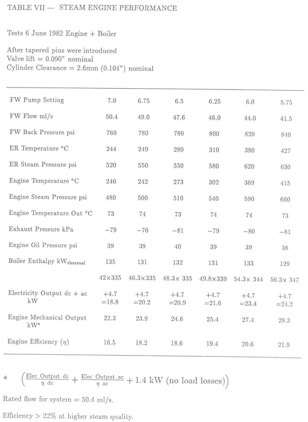
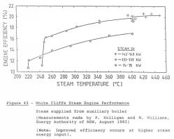
3.4.3 Performance
Table VII shows representative
performance characteristics and Figure 43
indicates efficiency varitions at different steam temperatures for
four different thermal power inputs - these measurements were made
by P. Holligan and M. Williams, NSW Energy Authority, in August
1983. It is apparent that efficiency drops slowly with reduction of
superheat until saturated steam results, after which operation on
wet steam causes a rapid reduction in efficiency as degree of
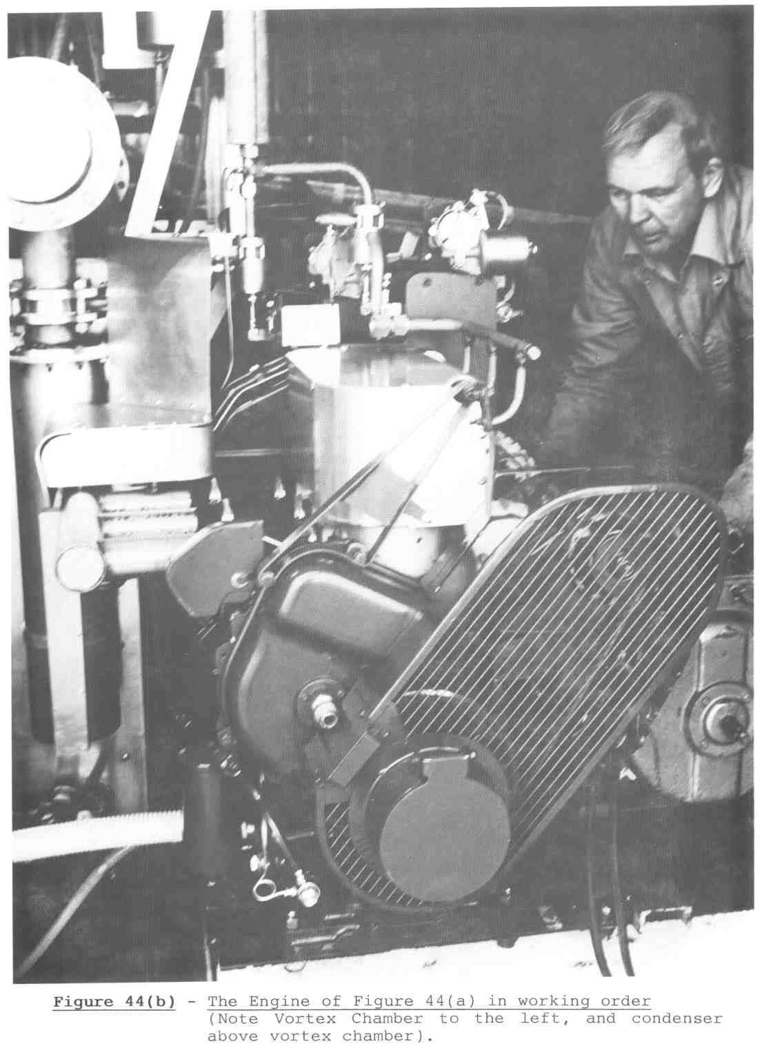
'wetness' increases. Figure 41 shows the engine at White Cliffs; a
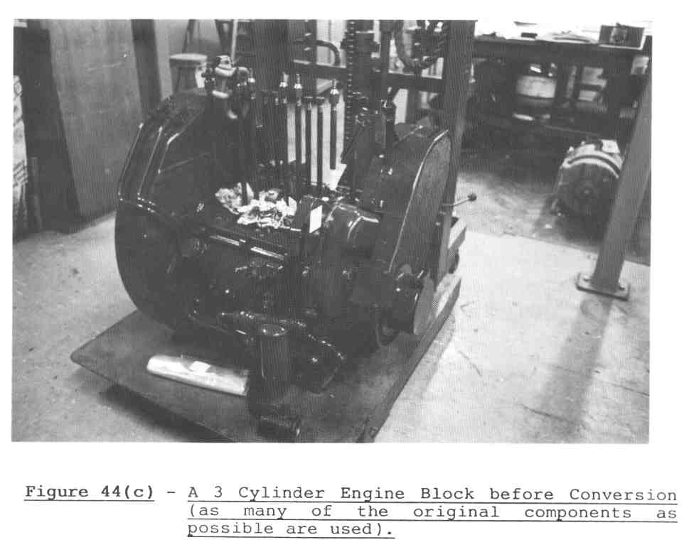
later version is indicated in Figures 44(a)
and (b); a block before conversion is shown
in Figure 44(c). Engine operation is
described in Section 1.1. We consider this engine technology has
good potential and scope for considerable further improvement.
Tables and Figures
As usual, click on the thumbnail images for the larger
versions.
 |
 |
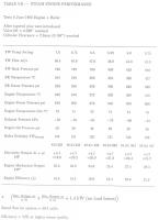 |
Figure 42 - Basic White Cliffs Engine Details showing
piston-operated valves, steam chambers, exhaust ports, and engine
block
JPEG 71k |
Figure 43 - White Cliffs Steam Engine Performance
JPEG 39k |
Table 7 - Steam Engine Performance
JPEG 59k |
 |
 |
 |
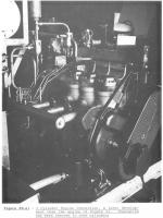
Figure 44(a) - 3 Cylinder Engine Conversion, a later
development than the engine of Figure 41. Insulation has been
removed to show the cylinders
JPEG 77k |
Figure 44(c) - A 3 Cylinder Engine Block before
Conversion (as many of the original components as possible are
used).
JPEG 36k |
Figure 44(b) - The Engine of Figure 44(a) in working
order (Note Vortex Chamber to the left, and condenser above vortex
chamber).
JPEG 83k |
--
Erik Rossen <rossen@rossen.ch>
OpenPGP key: 2935D0B9
Tel: +41 78 617 72 83
Home URL: http://www.rossen.ch
Copyright © 2000 until the heat-death of the Universe (thanks, Mickey!), by Erik Rossen
Last modified: 2016-02-07T12:43:25+0100
HOME -> SOLAR + HELIOSTATS -> WHITE-CLIFFS REPORT | SITEMAP